Triggered streaming is currently only supported by the UE9 and UE9-Pro, however you should contact LabJack if you have a different U series device to see if they have added this functionality. We aren't always able to keep up with new features of LabJack devices, but the software should handle anything new.
Triggered streaming is similar to regular streaming except instead of using the internal LabJack clock to determine when a scan of the stream channels occurs, an external pulse triggers the scan. The interval between external pulses must be less than the maximum stream rate for the current input resolution. The external pulses do not need to occur at a constant interval. To enable external triggering, just add the following line of script before adding your stream channels using LJ_ioADD_STREAM_CHANNEL:
AddRequest(ID, LJ_ioPUT_CONFIG, LJ_chSTREAM_EXTERNAL_TRIGGER, 1, 0, 0)
The trigger input will be the first available FIO pin based on which timers and counters you have enabled.
The only problem with triggered streaming is that the time of each data point will be off. This is because the LabJack buffers the scans and DAQFactory doesn't actually get the data until a full packet occurs. DAQFactory doesn't realize this and assigns times based on an assumed interval. If you have the bandwidth, i.e. your pulses are slow enough that you aren't close to the stream interval limit, you can use the system timer mode of the timers to retrieve exact relative times of your scans. To do this, you need to setup a timer for system timer in, and then add the timer to the list of channels to stream. Depending on how long your experiment runs, you may be able to get away with only SYSTIMERLOW. For the UE9 at 750khz, the low timer will roll over every 5726 seconds. Here's how to do it:
1) Enable two Timers:
AddRequest(ID, LJ_ioPUT_CONFIG, LJ_chNUMBER_TIMERS_ENABLED, 2, 0, 0)
2) Set the mode:
AddRequest(ID, LJ_ioPUT_TIMER_MODE, 0, LJ_tmSYSTIMERLOW, 0, 0)
AddRequest(ID, LJ_ioPUT_TIMER_MODE, 1, LJ_tmSYSTIMERHIGH, 0, 0)
GoOne(ID)
3) Set up the stream to stream analog input 2 and 3 in external trigger mode:
AddRequest(ID, LJ_ioPUT_CONFIG, LJ_chSTREAM_EXTERNAL_TRIGGER, 1, 0, 0)
// setup channels to stream:
AddRequest(ID, LJ_ioCLEAR_STREAM_CHANNELS, 0, 0, 0, 0)
AddRequest(ID, LJ_ioADD_STREAM_CHANNEL, 3, 0, 0, 0)
AddRequest(ID, LJ_ioADD_STREAM_CHANNEL, 4, 0, 0, 0)
4) Now we need to add our timers to the list of channels to stream. Make sure you use the order indicated:
AddRequest(ID, LJ_ioADD_STREAM_CHANNEL, 200, 0, 0, 0)
AddRequest(ID, LJ_ioADD_STREAM_CHANNEL, 224, 0, 0, 0)
AddRequest(ID, LJ_ioADD_STREAM_CHANNEL, 201, 0, 0, 0)
AddRequest(ID, LJ_ioADD_STREAM_CHANNEL, 225, 0, 0, 0)
5) Now finish up the stream setup:
GoOne(ID)
// start the stream:
global scanrate = 0
eGet(ID,LJ_ioSTART_STREAM, 0, @scanrate, 0)
// scanrate now has the actual scanrate, which you can display on the screen if you want.
6) Create 4 channels to receive this timing data in addition to the 2 you created to receive the analog input. All 6 channels are I/O type: A to D, Timing = 0. Channel #'s will be 3, 4, 200, 201, 224, and 225.
That completes it. When you run your script, the stream will start, streaming both analog inputs 2 and 3 as well as the system timer. A scan will occur every time a trigger is detected on FIO2. FIO0 and FIO1 are used by the 2 timers. With each scan, your six channels will update. The time associated with these channels will be incorrect, but channels 200, 224, 201, and 225 will contain the 4 words that make up the 64 bit system timer value. While this is not absolute time, it will give you relative time between each triggered scan. Just use the difference in counts divided by the system clock speed of 750khz for the UE9 to determine the actual number of seconds between scans. The best way to do this is to create a calculated V channel:
7) Right click on CHANNELS: under V: in the Workspace. Note this is note the same CHANNELS: that we've been clicking before. Select Add V Channel
8) Call the new channel TheTime
9) Click on the new channel in the workspace. In the Expression window, put:
(TimerLowLow + TimerLowHigh*2^16 + TimerHighLow * 2^32 + TimerHighHigh * 2^48)
This assumes you named channel 200 TimerLowLow, 224 TimerLowHigh, 201 TimerHighLow, and 225 TimerHighHigh. You also may want to put a divisor at the end to convert to seconds:
UE9: (TimerLowLow + TimerLowHigh*2^16 + TimerHighLow * 2^32 + TimerHighHigh * 2^48) / 750000
10) Click Apply.
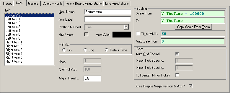
At this point, you can reference this channel like you would any other, except putting V. in front of it. Instead of getting a channel reading, you'll get the result of the calculation. Since we didn't use any [0] notation, this is the entire array calculated from all the readings. If you want to graph your channels, you'd put:
V.TheTime
as the X Expression in place of Time. You'll need to change the bottom axis type to Lin, undo Use Time Width, and adjust the Scale From and Scale To: