Now that you have a device created with your port settings and protocol we can create channels to communicate with your device. In this part, we will add a channel to the document and start acquiring data.
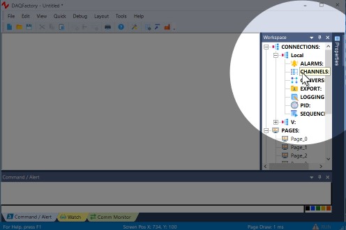
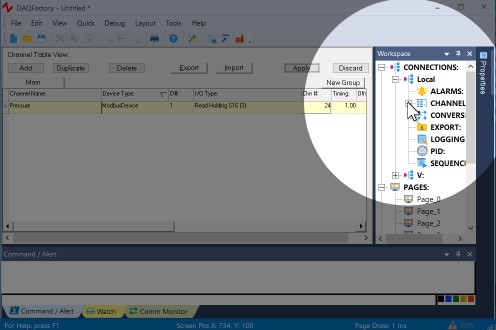
1. In the Workspace (the tree area along the right of the screen), click on CHANNELS: under Local.
The workspace provides an organized presentation of the different configuration screens for setting up your DAQFactory document. Clicking on almost every item in the tree will bring up a new view related to the item selected. Clicking on CHANNELS: displays the channel table where you can manipulate all the channels in your document. Make sure and click the CHANNELS: under Local and not the one under V:
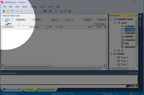
2. In the Channel Table View that appears, click on the Add button at the top.
This creates a new row where we will enter the information for our first channel.
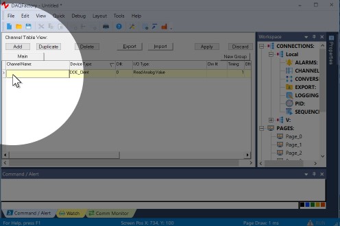
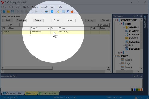
3. In the new row of the table, enter Pressure in the Channel Name column.
All channels must have a name. You can assign any name you want to your channels as long as they are unique, start with a letter and only contain letters, numbers or the underscore "_".
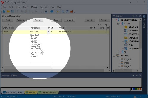
4. In the second column, Device Type, select ModbusDevice from the drop down list.
The device type determines which type of device you wish to communicate with. This can be a specific manufacturer, a specific device, or a generic communications method such as OPC. In our case, we select the device we just created that has our port settings and protocol. If you do not see the device and you are sure you created it, try leaving the channel view by clicking on one of the Pages in the workspace, then coming back.
5. In the third column, D#, enter the Modbus ID of your hardware. This usually defaults to 1 for most hardware, but you'll have to refer to your device settings for the proper value.
The device # is only used by some device types and has different meanings depending on the device. For Modbus the device # is the device ID.
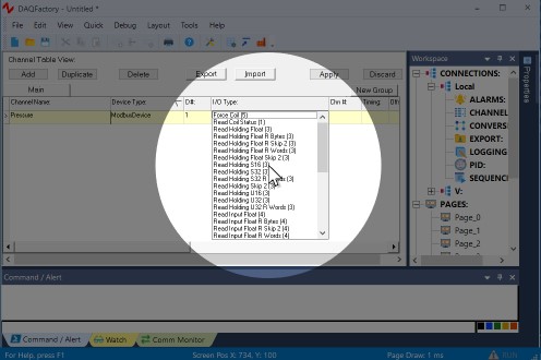
6. In the fourth column, I/O Type, select Read Holding S16 (3) or select from any of the other Modbus register types depending on your hardware.
Modbus technically only supports 6 different I/O types, force / read coil, read input status, read / write holding register and read input register. However, hardware manufacturers have "enhanced" Modbus by combining multiple registers in various ways to achieve registers with non-standard types like 32 bit integers and floating point values out of the standard 16 bit Modbus register. You should refer to your hardware documentation to see which type applies. Sometimes, especially with the various floating point types, it is not clear from the documentation which is appropriate. In this case you will often simply have to try each one until you get the proper values.
7. In the fifth column, Chn #, enter the Modbus register address you wish to read. There is no fallback here, you will have to look in your hardware manual.
Modbus addressing falls into two categories, what we call zero indexed and 40,000 notation. You can use either here and DAQFactory will automatically adjust. The only exception is if your hardware manual uses zero indexed and has registers that get up into the 30,000 and 40,000 range. In this case you will need to read a register in the 50,000 range (even if it doesn't exist) to fix DAQFactory into zero index mode. See the section on Modbus Protocols for more information.
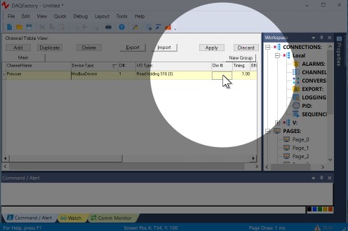
8. Leave the rest of the columns in their default setting.
One important item to mention is the sixth column, Timing. For input channels this determines how often the input is read from the device. The interval provided here is in seconds. For now, we are going to leave it set at 1, or one new reading per second. In general you will never want to make this number smaller than 0.01 and for Modbus even that is probably too fast for most hardware.
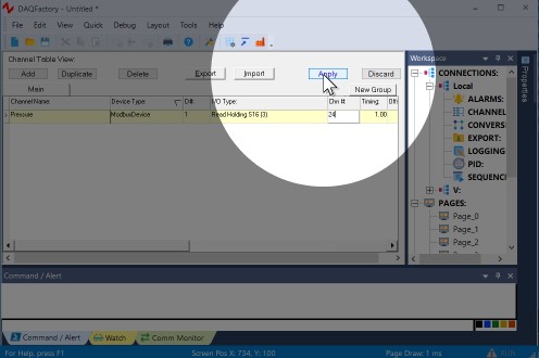
9. Click on the Apply button at the top of the screen.
The changes you make are not implemented by DAQFactory until you click Apply. If you do not want to keep your changes, you can click Discard. Once you click Apply, DAQFactory will start taking trying to take data from the Modbus device, and will place that data in the "Pressure" channel.
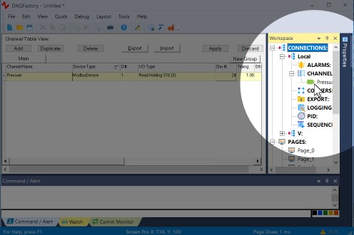
10. Click on the + sign next to CHANNELS in the workspace.
The + sign appeared when you hit Apply. Clicking on it displays the channels you've created as separate items in the workspace.
11. Click on Pressure listed under CHANNELS in the workspace.
This will display the channel view for the channel Pressure. The channel view displays the configuration information for a single channel. In general, it is quicker to create your channels in the channel table, but the channel view provides space for some extra details.
12. In the Channel View that appears, click on the Table tab.
The channel view also provides a table to view your incoming data. This can be used to confirm that data is being acquired and that you are reading the correct data. You should see numbers displayed in the table corresponding to your signal. You have just confirmed that you are acquiring data on your pressure channel.
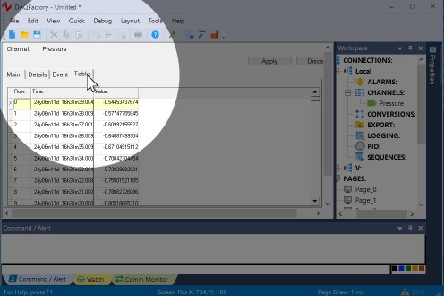
If you aren't seeing any data we'll go over some troubleshooting tips next.
For more information on channels and the various parameters available, see the chapter on Channels and Conversions.