In addition to taking data, most systems also control outputs. Here DAQFactory offers many advanced automated control features such as PID loop control and sequences, but for now we will just create an output channel and control it manually from a page component.
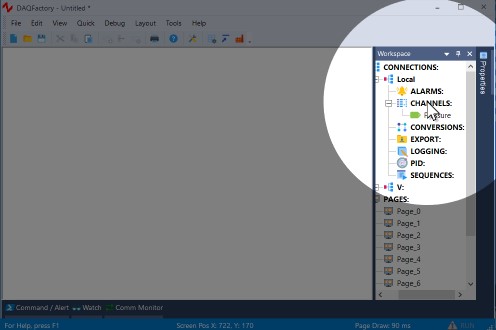
1. Click on CHANNELS: in the workspace to go back to the channel table.
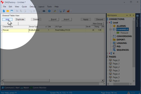
2. Click on Add to create a new row in the table.
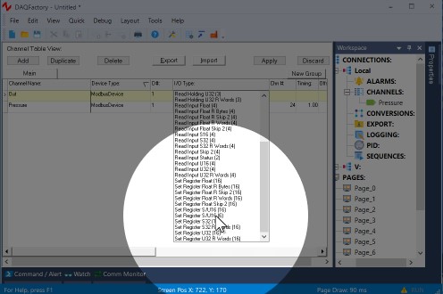
3. In the new row, name the channel Out. Select the same Device type and enter the same D# you used for Pressure, then select one of the output I/O types (Force Coil or one of the Set Register types) and enter the Modbus register address for the desired output. Leave the rest in their defaults.
4. Click on Apply to save your changes.
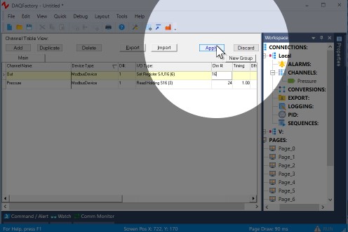
The output channel has been created, but it hasn't been set to anything. We'll see how to do that in a bit...
We will create some screen controls to set this output in section 2.8.
Proceed to section 2.6 and we'll display our new input channel on our own custom screens.
For more information on channels and the various parameters available, see the chapter on Channels and Conversions.